previously → saw that a moving magnet → induces e.m.f or current in nearby conductor.
- likewise → moving conductor in the presence of a magnetic field will also produce an e.m.f or current in the conductor.
- referred to as generator effect
Just as in motor effect → there is r.s. between the direction of applied force, magnetic force and current.
- relationship is given by Fleming’s Right Hand Rule
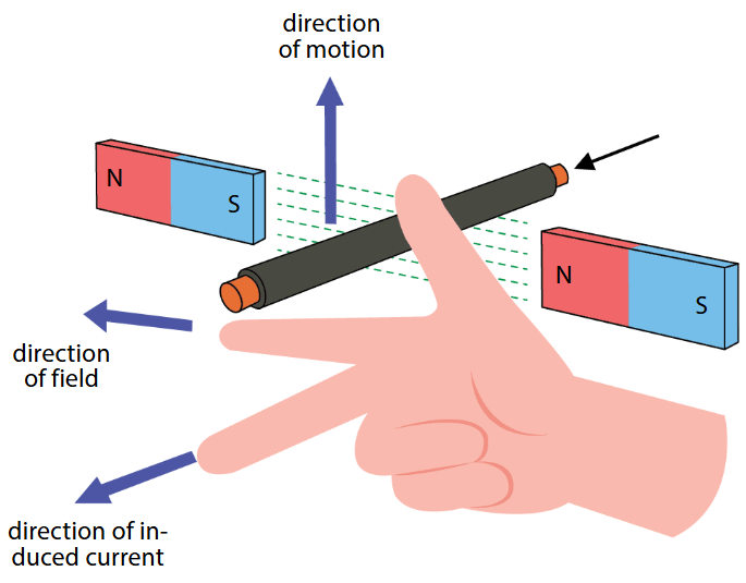
Direction of conventional current → determined using Fleming’s right hand rule.
- First, right hand held out with forefinger, second finger and thumb perpendicular to each other
- Next, thumb is pointed in the direction of motion of the conductor and first finger in the direction of the magnetic field, from north to south. → direction of conventional current is given by the direction the second finger is pointing to.
Flemings left hand rule → is used for electric motors, While Flemings right hand rule is used for generators.
- important not to confuse 2
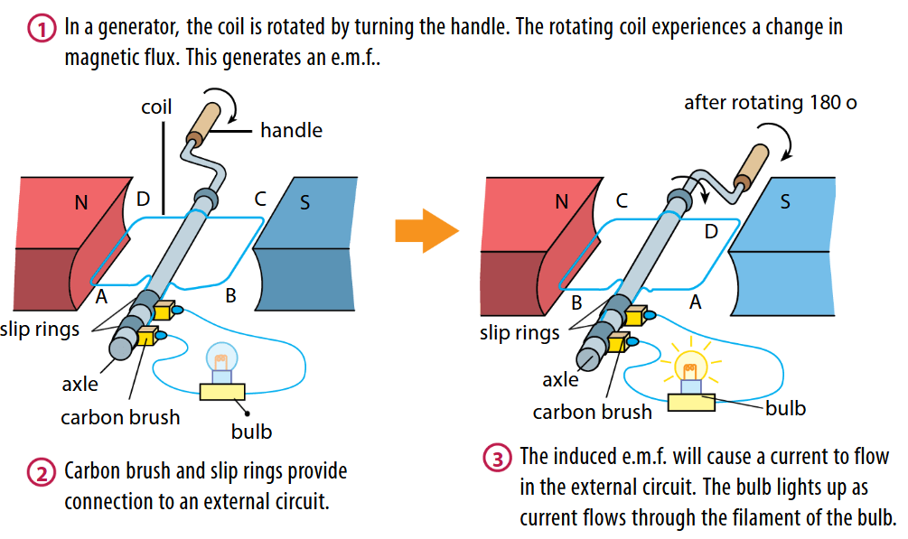
consider case of rectangular coil → that is mounted on an axle rotating between 2 permanent magnets.
-
Due to rotation → continuous flow of current is induced in the rectangular coil.
-
direction of the current flow is given by Fleming’s right hand rule and is in the direction of A to D.
-
as the coil flips after 1/2 a revolution → induced current changes direction and is now flowing from D to A.
-
similarly → current is initially flowing from C to B.
-
after half a revolution → current flows from B to C.
-
current alternates and is known as an alternating current
-
an alternating current → is produced by an alternating induced e.m.f.
-
therefore → such generators are more specifically termed as alternating current (a.c.) generators or alternators.
-
an important difference between d.c. motor and a.c. generator → is the use of slip rings in an a.c. generator.
-
slip rings are important → as the make sure that the ends of the rotating rectangular coil do not get twisted together as the rectangular coil rotates
-
slip rings also provide the electric contact with the brushes so that electric current can flow continuously in the a.c. generator
-
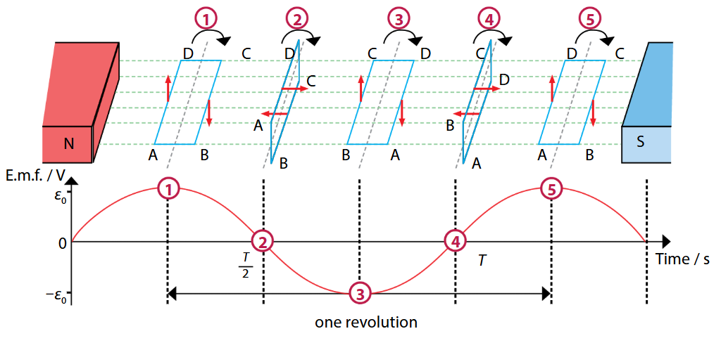
as the current and voltage of an a.c. generator alternates → the e.m.f goes through a maximum to 0 to minimum transition.
-
indeed, as the coil rotates through diff. positions → the amount of induced e.m.f changes
-
amount of e.m.f induced also depends on the rate at which coil cuts the magnetic field lines.
| Explanation |
|---|
| At position 1 → the rate at which AD and BC → cut the magnetic field lines is the greatest since the movement of the coil is perpendicular to the magnetic field lines. → hence the magnitude of the induced e.m.f is also the greatest. |
| At position 2 → AD and BC → do not cut the magnetic field lines since the movement of the coil → would be parallel to the direction of field lines. → hence the magnitude of the induced e.m.f. is 0 |
| At position 3 → the rate at which AD and BC → cut the magnetic field lines → is the greatest. However → since induced current in the coil is flowing in the reverse direction → the induced e.m.f. is also in the opposite direction to that at position 1. e.m.f. is negative to indicate the change in direction |
| At position 4 → AD and BC once again do not cut the magnetic field lines. → hence magnitude of induced e.m.f. is 0 |
| At position 5 → coil returns to its starting point → after having completed 1 revolution. rate at which AD and BC cut the field lines once again is the greatest and the magnitude of the induced e.m.f. is the greatest. |
| from above figure → we can see see that if the coil is rotated through 1 complete revolution → the induced e.m.f. also moves through 1 complete cycle of a sinusoidal wave form. |
| The time it takes to complete 1 cycle is the periodic time T. |
| Number of revolutions the coil makes in 1 second is its frequency. |