- there are 3 rays passing through a converging lens that can be drawn accurately in ray diagrams.
- these rays are useful → help us locate where image point will be for a given point on an object
| Ray 1: Passes through Optical Centre C | Ray 2: Parallel to Principal Axis | Ray 3: Passes through Focal Point F |
|---|---|---|
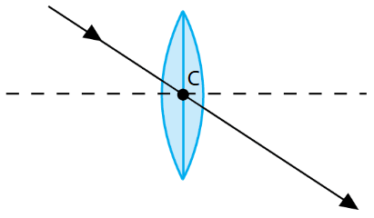 | 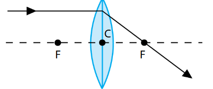 | 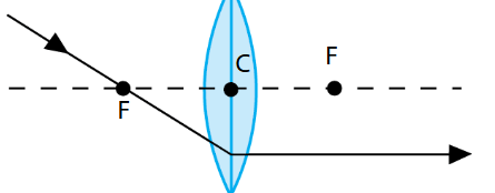 |
| - Incident ray will pass through optical centre → without bending - Recall that emergent ray is parallel to incident ray and that shift is small if the lens is thin | - Incident Ray parallel to the principal axis is refracted to pass through the principal focal point F | - Incident ray passing through principal focal point F before passing through the lens will emerge parallel to the principal axis (principle of reversibility) |
| → any 2 of the rays in the above figures from a given object point will intersect at a point → which is where the image point is. |
Steps to Draw:
Steps
Step 1:
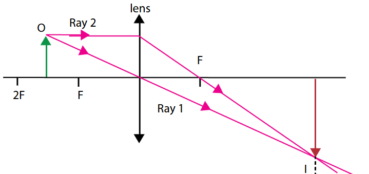
- set up the reference points and horizontal axis as shown.
- double arrow represents the lens
Step 2:
- Draw the object O (green)
- Rays 1 and 2 → used to locate the image at point l
- the point where the 2 rays intersect corresponds to the object point O at the arrow tip.
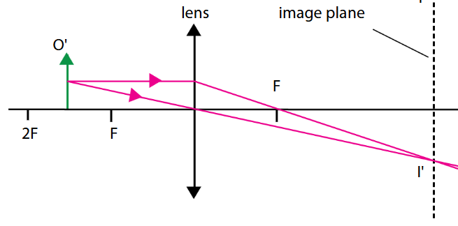
Step 3: Every point on the image will have a corresponding image point
- construction of rays for object point O’ will give rise to its image point I’
- if done accurately → all image point swill fall on the image plane indicated by the dotted line
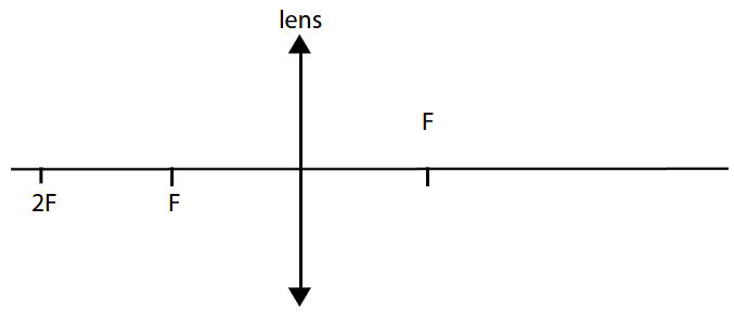
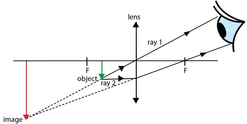
- ray diagram for thin converging lens where the object is downward arrow between F and the optical centre
→ in this diagram → you can see that the light rays do not intersect after passing through the lens. → they intersect on the same side as the object when they are extended. When light rays enter our eyes → they appear to come from the same side as the object.
- if you were to repeat the construction of rays for other points of the object → you will find that the image plane is along the red arrow.
- notice that the whole image as seen by the observer → appears to be magnified → compared to actual object.